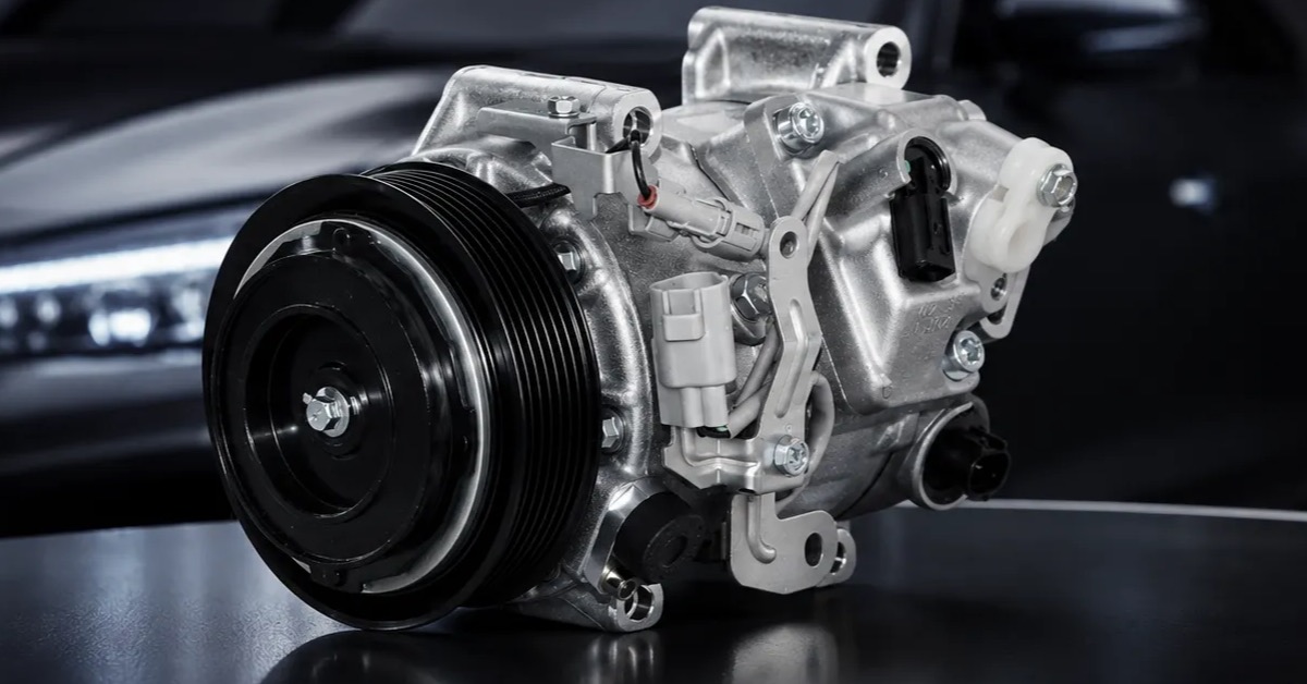
An automotive cooling fan assembly should be evaluated as a pressure-producing air-moving system, not as a motor that spins a blade in open air. The result depends on fan, shroud, radiator or condenser stack, inlet and outlet restrictions, speed, voltage, temperature, recirculation, and the measurement plane. A free-air airflow number can look impressive while the installed stack still overheats or consumes too much power.
This ZUA Auto Parts resource helps distributors organize the evidence needed before quotation; confirm the exact application, interfaces, tests, and supplied scope for every requested part.
A decision-ready test reveals a pressure-flow curve and the conditions behind it. It also identifies whether a supplier is delivering a motor, fan-and-shroud assembly, complete module, or a vehicle-specific package.
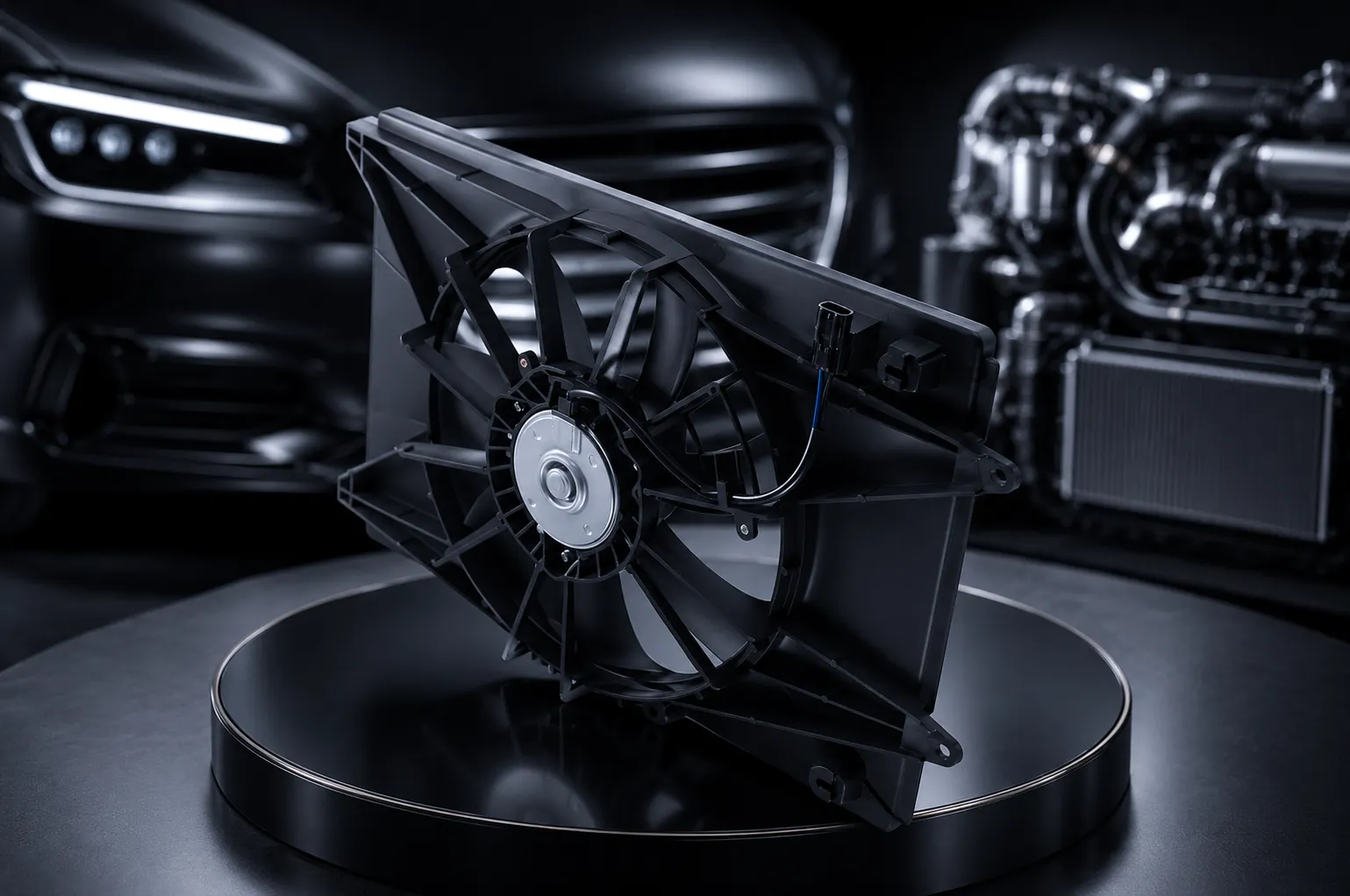
Define the air path before selecting instruments
Draw the inlet, fan, shroud, heat exchanger, outlet, bypass, and recirculation path. Mark the pressure taps, airflow plane, temperature sensors, electrical measurement points, and obstructions. State whether the fan pushes or pulls and which vehicle-side components are included.
Use the same geometry for candidate comparisons. Changing the shroud, radiator spacing, grille, filter, or duct can change the measured curve more than changing the motor.
The test report fields that matter
| Measurement | Record | What it explains |
|---|---|---|
| Airflow | Flow, plane, instrument, uncertainty | Delivered air movement |
| Pressure | Static or differential points, taps, condition | Resistance and system operating point |
| Speed | RPM, command, stability, direction | Fan operating state |
| Electrical | Voltage, current, power, command | Load and control demand |
| Thermal | Ambient, inlet, outlet, soak, stabilization | Temperature context |
| Acoustic | Location, distance, speed, background | Noise comparison |
Measure an automotive cooling fan assembly as a curve, not a headline point
Run several operating points across the relevant command or voltage range. Plot airflow against pressure and annotate speed, power, and temperature. Identify stall, recirculation, saturation, unstable control, and the range where the assembly becomes inefficient.
For an automotive cooling fan assembly, the vehicle operating point may move with radiator restriction, condenser load, vehicle speed, grille condition, and engine bay temperature. A curve gives the buyer a way to compare that moving point.
Keep shroud fit in the measurement
The shroud seals the fan to the heat exchanger and controls leakage around the blade. Record flange contact, gaps, fasteners, foam or seals, blade-to-shroud clearance, overlap, and local distortion. A shroud that fits one fixture loosely can make the fan look weak; a shroud that is forced into place can hide production risk.
Photograph the installed stack and measure the clearances that affect assembly and service. The test fixture should reproduce critical gaps or state them as limitations.
Control voltage, command, and temperature
Record supply at the module terminals under load, command signal, ground drop, current, power, and thermal state. For electronically controlled fans, freeze communication or PWM assumptions and diagnostic behavior. Do not compare one fan at a cold room condition with another after heat soak.
When a customer specification defines voltage or transient exposure, use it. Otherwise report the tested conditions and avoid presenting them as universal limits.
Separate fan, motor, and module scope
A bare motor, motor-and-blade unit, fan-and-shroud assembly, and complete cooling module answer different procurement questions. State the delivered scope, transfer parts, connectors, brackets, sensors, fasteners, and calibration or control responsibility.
This scope belongs in the sample label, test report, catalog, quote, and warranty record. Otherwise a measured module can be sold as if it were a motor-only replacement.
Use thermal load to make airflow meaningful
Pair airflow measurement with a defined heat-exchanger or thermal load when the program requires performance evidence. Record coolant or refrigerant context, inlet temperatures, heat load, airflow distribution, and stabilization. The purpose is to link the fan curve to the temperature outcome without claiming that one bench represents every vehicle.
Inspect hot spots, uneven flow, bypass leakage, fan cycling, and controller response. These observations often reveal a stack problem that a single centerline airflow reading misses.
Capture noise and vibration with operating state
Record microphone location, background, speed, command, temperature, mounting, and whether the sound comes from motor, blade, shroud, bearing, or surrounding panels. Pair acoustic data with runout, balance, current, RPM, and visual inspection.
Do not use “quiet” as a stand-alone claim. The accepted sound level depends on the vehicle, measurement method, and operating point.
Make durability follow the installed constraint
Define vibration, shock, humidity, dust, corrosion, temperature, voltage, cycling, obstruction, and shipping exposure according to the installation and customer specification. The ISO 16750-3 overview provides context for mechanical loads on road-vehicle electrical and electronic equipment; it does not replace the fan program's levels or acceptance criteria.
After exposure, repeat airflow, pressure, speed, current, noise, runout, connector retention, and visual checks. Keep before-and-after traces linked to the same sample and configuration.
Use a fault-isolation sequence
When airflow is low, first check voltage and ground under load, command, speed, rotation, wheel geometry, shroud gaps, heat-exchanger restriction, and bypass leakage. When current is high, check voltage, bearing, blade contact, imbalance, obstruction, and controller behavior. When temperature remains high, verify thermal load, coolant or refrigerant conditions, airflow distribution, and vehicle speed context.
This sequence prevents a fan replacement from hiding a blocked stack, wrong rotation, poor seal, or electrical resistance.
Compare variants by the operating point they serve
When two fan assemblies share a motor family, compare their pressure-flow curves, shroud openings, blade geometry, speed range, power, control method, and heat-exchanger stack rather than assuming the higher free-air flow is better. One variant may be designed for a restrictive condenser stack, another for a larger radiator, and a third for a different vehicle package.
Record the chosen operating point and the reason for selection in the approval file. If a distributor lists alternatives, show which vehicle data determines the choice. This keeps an automotive cooling fan assembly page useful for both search visitors and technical buyers instead of turning several distinct modules into interchangeable-looking thumbnails.
State the measurement uncertainty and repeatability
Record instrument range, calibration status, sampling rate, fixture repeatability, ambient stability, and the number of repeats used at each operating point. If the fan is close to an acceptance boundary, repeat the point after reinstallation or use a retained reference to show whether the shift comes from the assembly or the bench.
Report the uncertainty beside the result instead of presenting every decimal as meaningful. For an automotive cooling fan assembly, a small change in shroud gap, pressure tap, blade position, or voltage can move airflow. Repeatability data helps the buyer distinguish a real supplier difference from normal measurement variation and gives quality teams a defensible reaction rule.
Publish the operating envelope beside the test curve
Annotate the pressure-flow chart with the tested voltage, command range, speed, temperature, heat-exchanger restriction, shroud, and mounting direction. State which conditions are outside the test. This keeps a buyer from copying one curve into a different vehicle stack without understanding the boundary.
If the assembly has a controller, show the command points and any protection or derating state used during measurement. If it is a simple motor and blade, state the external controller and shroud assumed by the test. An automotive cooling fan assembly page that exposes its operating envelope creates better inquiries because customers can provide the missing stack data before asking for a quote.
Ask ZUA for the assembly boundary
ZUA lists cooling fan assemblies within its engine-cooling product range. Buyers can review the wider portfolio, read company information, and send the vehicle stack, test points, sample needs, and forecast through the contact page.
Confirm whether the requested unit is a fan, motor, shroud assembly, or complete module, and agree on airflow, pressure, electrical, thermal, acoustic, durability, and packaging evidence for the quoted SKU.
Frequently asked questions
Why is free-air airflow insufficient?
It does not represent pressure resistance, shroud leakage, heat-exchanger restriction, or the installed operating point.
What should a fan test report include?
Include flow, pressure, speed, voltage, current, power, temperatures, command, configuration, instruments, and uncertainty.
Does the shroud affect airflow?
Yes. It controls bypass leakage, blade clearance, flow distribution, and the connection to the heat exchanger.
Should tests use several speeds?
Use the command or speed points relevant to the vehicle and customer specification, not one arbitrary point.
What is the difference between a module and a motor?
A module may include blade, shroud, controller, sensors, brackets, and hardware that are absent from a motor-only part.
How can high current be investigated?
Check voltage, ground, bearing drag, blade contact, obstruction, imbalance, temperature, and controller behavior.
What makes a thermal fan test useful?
Use a defined heat load, airflow path, temperatures, stabilization, and recorded stack configuration.
How should noise be reported?
Report location, distance, background, speed, command, temperature, mounting, and supporting mechanical evidence.
When is durability evidence comparable?
It is comparable when sample configuration, fixture, exposure, measurement, and acceptance criteria are aligned.
How can buyers request ZUA fan data?
Send vehicle, stack, fan scope, test points, control interface, sample quantity, forecast, and evidence requirements.
Release the curve and the assembly
An automotive cooling fan assembly should be released with a known air path, pressure-flow evidence, shroud boundary, electrical state, thermal context, acoustic record, durability plan, and delivered scope. That makes supplier comparisons meaningful and gives field teams a better basis for diagnosing temperature complaints.