A thermostatic expansion valve automotive application must match the refrigerant circuit, evaporator, compressor behavior, connection geometry, sensing arrangement, operating range, and vehicle calibration. A valve that bolts on can still meter incorrectly, hunt, starve the evaporator, flood the outlet, create noise, or respond poorly during changing conditions.
For a ZUA Auto Parts inquiry, use this framework to separate confirmed product data from buyer-owned validation and open questions before approving a sample or order.
This guide is for distributors, sourcing engineers, private-label brands, and HVAC service networks comparing automotive TXVs. It explains system matching without assigning universal superheat, flow, pressure, or temperature values, because the design and customer requirement define them.
See the valve as part of a feedback system
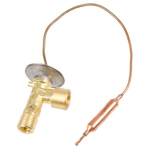
The TXV meters refrigerant toward the evaporator while responding to outlet temperature and pressure through its sensing and diaphragm mechanism. The balance of sensing force, evaporator pressure, and spring force changes the opening. Its purpose is not to hold one fixed orifice area but to manage refrigerant feed as load changes.
The observed result also depends on refrigerant charge, condenser heat rejection, liquid-line condition, evaporator airflow, compressor displacement or control, sensor placement, and the rest of the circuit. Diagnose the system before blaming one valve.
Write a system boundary before the test begins. Identify which items are fixed, which may be adjusted, which data channels are trusted, and which event triggers a stop. This prevents technicians from tuning refrigerant charge, airflow, or compressor command until a candidate appears acceptable.
Map every interface before selecting a part
| Interface | What to confirm | Risk if wrong |
|---|---|---|
| Refrigerant | Approved type and associated design | Incorrect response or material concern |
| Evaporator | Capacity, pressure drop, circuiting, outlet behavior | Starvation, flooding, instability |
| Compressor | Displacement, variable/fixed control, operating envelope | Poor system interaction |
| Connections | Port form, spacing, seal, fasteners, orientation | Leak or installation failure |
| Sensing | Internal/external equalization, bulb or block arrangement | Wrong control signal |
| Vehicle | Application, build boundary, HVAC option | False fitment |
| Controls | Pressure and temperature strategy, protective logic | Misdiagnosed behavior |
Confirm the exact valve architecture
Automotive systems may use block-type or other thermostatic valve arrangements, internal or external equalization, different sensing configurations, port layouts, inlet screens, and calibration features. Identify the original architecture from controlled drawings, OE data, sample inspection, and system evidence.
For a thermostatic expansion valve automotive replacement, external similarity is insufficient. Port passages and internal response can differ even when the mounting envelope looks alike.
Match the refrigerant and material system
Confirm the refrigerant specified for the vehicle and the valve design approval. Review sealing materials, lubricant compatibility, internal cleanliness, desiccant and circuit compatibility, manufacturing residues, and any material restrictions. Do not infer compatibility only because threads and seals connect.
If a market includes converted or incorrectly serviced vehicles, state the catalog limitation. A replacement part should be selected for the approved vehicle configuration, not used to validate an unknown conversion.
When local regulations or service practice affect refrigerant handling, use current official requirements for that market. The component approval remains a product and system decision; it should not be confused with authorization to change refrigerants.
Understand evaporator load and circuit behavior
The evaporator’s heat load, airflow, circuiting, pressure drop, distribution, and outlet condition influence the signal seen by the valve. Review operation at idle and speed, low and high blower, transient cabin pull-down, changing ambient, compressor-control transitions, and any rear-HVAC arrangement relevant to the vehicle.
A valve sized or calibrated for another evaporator may show acceptable behavior at one point but unstable feeding elsewhere. Use a representative operating matrix.
Account for compressor control strategy
Fixed-displacement, cycling, variable-displacement, and electrically controlled compressors interact differently with the rest of the system. Pressure regulation, clutch cycling, control-valve commands, speed, and protection logic can alter apparent TXV behavior.
When investigating oscillation, low capacity, or icing, record compressor command and displacement-related evidence where available. Replacing the expansion valve without understanding compressor control may only shift the symptom.
Do not diagnose from pressure readings alone
High-side and low-side pressure are valuable, but interpretation requires ambient, cabin, blower, airflow, engine speed, refrigerant charge, condenser fan operation, line temperatures, control state, and stabilization. Similar pressure patterns can result from different causes.
For thermostatic expansion valve automotive diagnosis, combine pressures with inlet and outlet temperatures, superheat-related analysis using the approved refrigerant data, airflow, visual icing pattern, command data, and known-good comparisons.
Use a symptom-to-evidence decision path
Evaporator appears starved
Check charge, liquid-line restriction, receiver drier, inlet screen, line condition, condenser performance, valve sensing, equalization, installation, and actual valve flow before declaring the valve under-sized.
Outlet appears too wet or unstable
Check sensing contact, insulation, valve response, charge, airflow, evaporator distribution, compressor control, and transient conditions. Preserve the exact operating point.
Cooling cycles or hunts
Plot pressures, temperatures, commands, and time. Determine whether the oscillation originates in valve feedback, compressor control, icing protection, fan control, airflow, or measurement delay.
Noise occurs near the valve
Assess refrigerant state, pressure drop, flow condition, charge, restriction, mounting transmission, and operating transition. Location of perceived sound does not prove the internal source.
Validate on a controlled system bench
A bench program should identify the complete circuit, instruments, refrigerant charge, lubricant, airflow, temperatures, compressor speed or command, stabilization, transient sequence, and acceptance source. Record valve and sample revision. Compare candidate and reference under equivalent conditions.
Relevant outputs may include cooling performance, refrigerant flow, pressure and temperature response, stability, evaporator distribution, restriction, leakage, and behavior after durability. The exact set depends on program objectives.
Before comparing samples, demonstrate that the bench can repeat the same reference valve after removal and reinstallation. Review sensor uncertainty, refrigerant charging, oil distribution, airflow, environmental drift, and stabilization. If bench variation approaches the difference between candidates, improve the method before ranking them.
Confirm behavior in the vehicle
Vehicle validation closes gaps from duct airflow, sensor locations, software, engine-bay heat, fan control, idle behavior, road speed, vibration, installation, and cabin load. Test representative configurations and document charge and service procedure.
Include pull-down and transitions, not only one stabilized point. A valve can appear acceptable after stabilization while responding poorly during the conditions customers notice.
Use several representative vehicles or system builds when production variation can affect the conclusion. The thermostatic expansion valve automotive result should record vehicle identity, software, HVAC option, and any deviations, so an outlier can be investigated instead of averaged away.
Protect cleanliness during storage and installation
Keep ports sealed until assembly, protect sealing faces, use clean tools, replace specified seals, control lubricant, and avoid exposing the circuit to open air longer than necessary. Follow the vehicle procedure for evacuation, charge, and oil balance. Contamination can obstruct small passages or hold the valve open.
When a failed system has debris or compressor damage, replacing only the valve may transfer contamination into the new part. Define circuit cleaning and component-replacement decisions from the repair requirement.
After installation, confirm leak integrity and system evacuation before charge. Record the service equipment, quantity added, oil action, ambient condition, and final operating check. For a thermostatic expansion valve automotive claim, this record helps separate product behavior from service variation.
Verify fitment and traceability at receiving
Check label, part number, lot, body marking, port layout, seal surfaces, protective caps, included hardware, and controlled dimensions. Use samples from actual production packaging, not only engineering prototypes. Preserve lot identity through warehouse and claim handling.
ZUA lists valves within its expansion devices and valves range. Buyers should confirm the responsible production route and request model-specific drawings, application evidence, test reports, and change responsibilities.
Control changes that can alter system response
Review changes to body, ports, seals, spring, diaphragm, power element, sensing charge, screen, equalization path, internal parts, materials, machining, cleaning, assembly, supplier, test method, software, or production site. Determine whether fitment, flow, response, leakage, durability, or cleanliness needs revalidation.
The IATF 16949 overview provides quality-system context. Buyers still need an agreed notification and approval route for the exact valve program.
Frequently asked questions
What does an automotive TXV control?
It meters refrigerant into the evaporator in response to forces related to outlet condition and evaporator pressure, within its design.
Can a physically identical valve have different performance?
Yes. Internal architecture, calibration, sensing, equalization, passages, materials, and production variation can affect response.
Do low suction pressures always mean a blocked TXV?
No. Charge, other restrictions, airflow, condenser performance, compressor control, sensors, and operating conditions can create similar readings.
Why does compressor type matter?
Compressor displacement and control affect pressure and flow behavior, which interact with valve response and vehicle protective logic.
Should a new valve be installed after compressor failure?
Follow the system repair requirement. Debris and contamination risk may require additional component replacement and circuit cleaning.
Can bench testing replace vehicle validation?
Not always. Vehicle airflow, controls, heat, packaging, software, vibration, and transient use can reveal different interactions.
Does ZUA supply expansion valves?
ZUA lists expansion devices and valves in its portfolio. Buyers should verify fitment, responsible production route, evidence, and program terms.
How can buyers request a valve quotation?
Send OE reference, vehicle configuration, refrigerant, sample or drawing, forecast, market, and validation needs through the ZUA contact page.
Match thermostatic expansion valve automotive behavior
A sound thermostatic expansion valve automotive decision links refrigerant, evaporator, compressor control, sensing, interfaces, operating range, clean installation, bench evidence, and vehicle validation. Diagnose the whole feedback system and approve the exact revision, not a visually similar body.