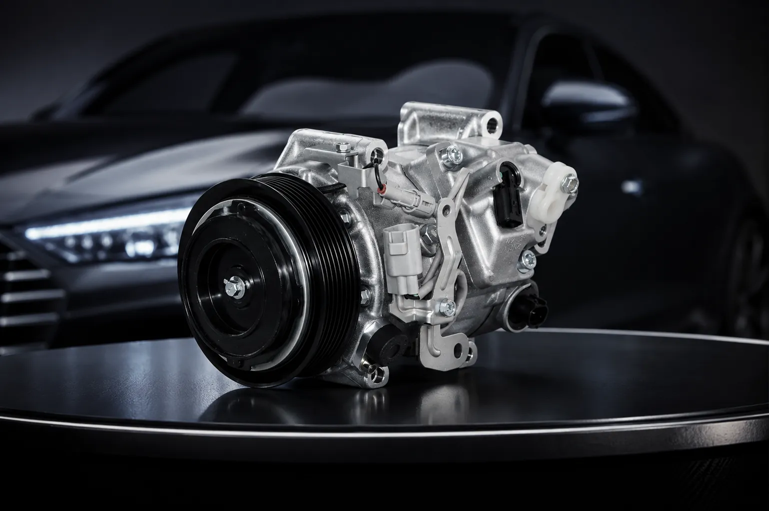
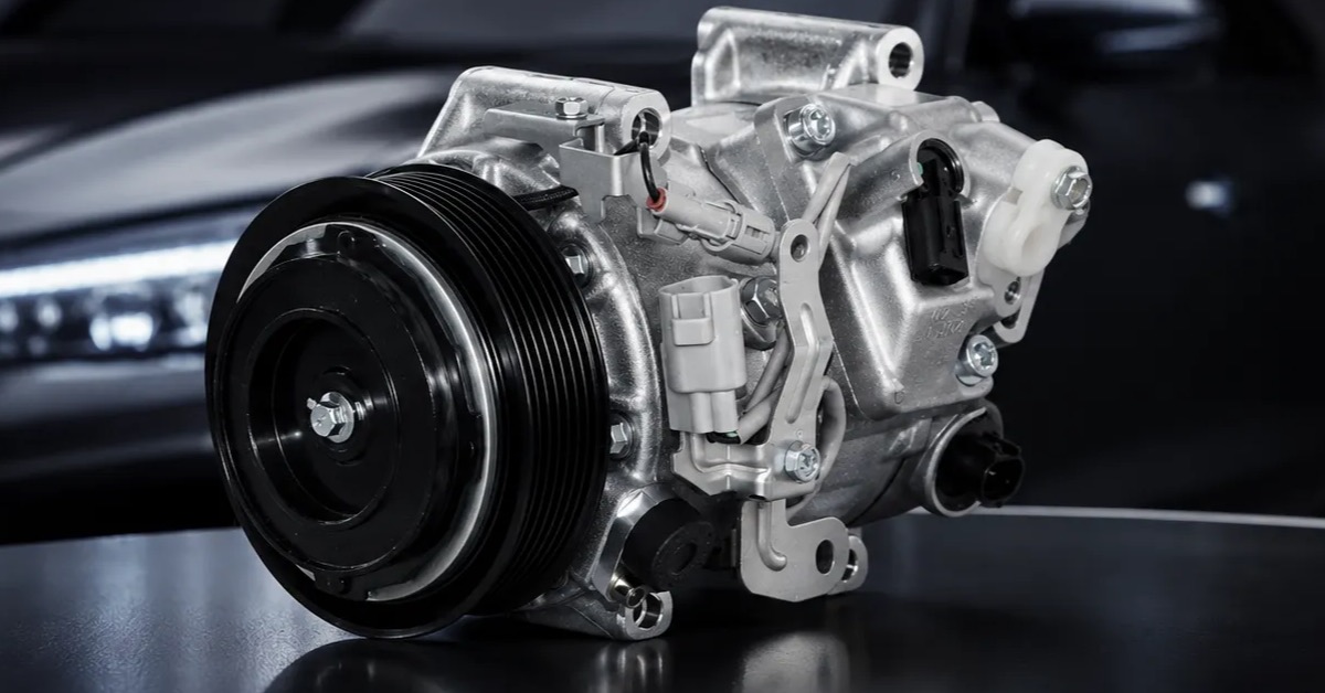
An externally controlled variable displacement compressor does not decide capacity from internal pressure balance alone. The vehicle, HVAC controller, powertrain controller, or a dedicated control strategy sends an electrical command to a regulating valve. That valve changes the compressor's internal control pressure, which changes swash-plate angle, piston stroke, displacement, refrigerant flow, shaft load, and cooling output. Buyers therefore need to qualify the compressor and its command environment as one system.
For buyers sourcing through ZUA Auto Parts, this framework connects the technical question to a controlled product inquiry; exact fitment and quoted specifications remain SKU-specific.
This distinction matters when a compressor fits the bracket and belt but still cools poorly, loads the engine unexpectedly, stores a fault code, or behaves differently at idle. The fastest route to a reliable approval is to map every signal, interface, operating state, and acceptance record before the first sample is installed.
Start with the command path, not the catalog photo
Draw a single-page signal chain: cabin request, sensor inputs, controller decision, command waveform or current, harness, connector, regulating valve, internal pressure change, displacement response, suction and discharge condition, vent result, and diagnostic feedback. Place the responsible organization beside each link. This exposes gaps that a part-number cross-reference cannot show.
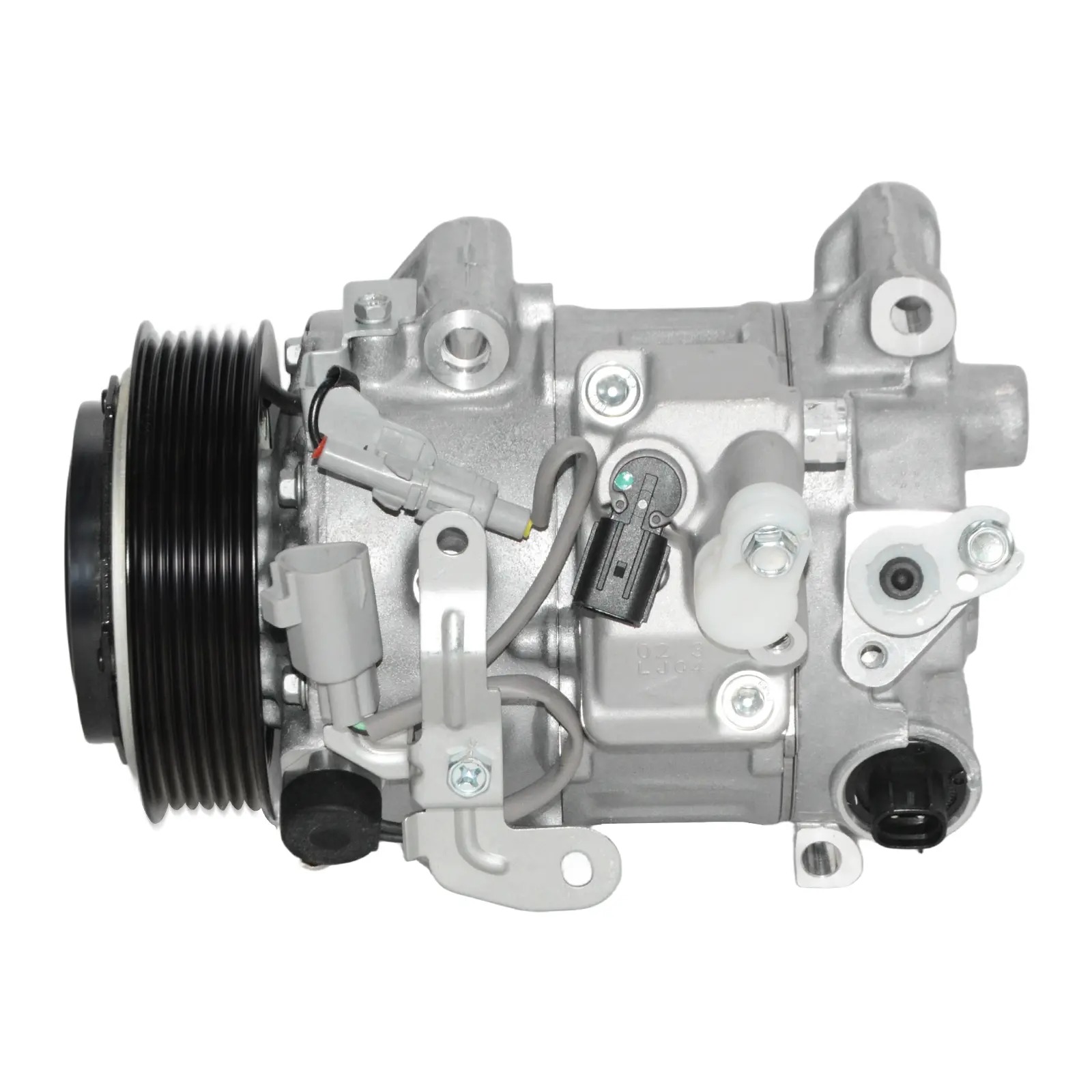
At minimum, record supply voltage, ground strategy, connector keying, terminal assignment, control type, command range, frequency if pulse-width modulation is used, current limits, diagnostic behavior, default state, and expected response under defined operating conditions. Do not assume two visually identical valves use the same command logic.
A buyer decision table for electronic control matching
| Decision layer | Evidence to request | Failure if ignored |
|---|---|---|
| Mechanical fit | Mounts, pulley, belt line, ports, envelope | Interference, belt wear, installation failure |
| Refrigerant circuit | Refrigerant, oil, charge, heat exchangers, valve type | Wrong pressure and temperature response |
| Electrical interface | Pinout, resistance, current, waveform, polarity | No control, fault code, valve damage |
| Control strategy | Command map, sensor logic, protection states | Unstable or inappropriate displacement |
| Dynamic performance | Response time, overshoot, steady-state capacity | Slow pull-down or cycling complaints |
| Diagnostics | Fault thresholds, default position, recovery rule | Incorrect troubleshooting and returns |
Separate valve identity from compressor identity
The control valve is not a generic accessory. Its electrical characteristics, hydraulic behavior, filtration, sealing, calibration, and mechanical interface affect the complete unit. A compressor family may use several valve variants for different vehicle controls. Freeze the valve maker, part number, revision, connector, coil data, calibration boundary, and approved alternatives in the bill of material.
For an externally controlled variable displacement compressor, a silent valve substitution can shift minimum displacement, response time, current draw, or fail-safe behavior without changing the compressor housing. Change control should therefore require technical review, sample identification, test evidence, inventory separation, and buyer notification.
Define the operating states that matter
A bench result at one speed and one ambient condition is not enough. Build a state matrix covering engine start, hot soak, cold start, idle, acceleration, deceleration, high humidity, low airflow, maximum cooling, partial load, defrost, protection mode, stop-start operation, and command loss. Add any hybrid or electric-vehicle conditions only when they apply to the program.
For every state, specify compressor speed, command, inlet condition, outlet condition, condensing airflow, evaporator airflow, target pressure behavior, temperature response, torque or power observation, and stabilization time. The matrix becomes the bridge between component testing and vehicle symptoms.
Read response as a curve instead of a pass/fail point
Plot command against displacement proxy, mass flow, suction pressure, discharge pressure, torque, or cooling output under controlled conditions. Look for dead bands, hysteresis, nonlinearity, delayed response, saturation, oscillation, and temperature dependence. A unit can pass at maximum command yet respond poorly in the middle of the control range where the vehicle operates most often.
Compare new samples, retained references, and aged samples on the same chart. Define measurement uncertainty and stabilization rules. If the buyer and supplier use different benches, agree on a correlation study rather than debating isolated numbers.
Freeze the refrigerant and lubricant context
Record refrigerant, lubricant type, lubricant quantity, system charge, residual oil assumptions, flushing condition, service parts, and contamination limits. Capacity control can be distorted by an incorrect charge, mixed oil, restriction, air, moisture, or debris. A compressor should not be blamed until the surrounding circuit is documented.
The supplier should state the delivered oil condition and shipping protection. The installer or laboratory should record any oil adjustment. This chain of custody is essential when an externally controlled variable displacement compressor is analyzed after a cooling complaint.
Test electrical loads without inventing universal limits
Vehicle electrical systems can expose components to supply variation and transient events. The applicable test levels depend on mounting location, vehicle architecture, customer specification, and component design. The current ISO 16750-2 overview provides context for electrical loads on road-vehicle electrical and electronic equipment; it is not a substitute for the program specification.
Agree on normal voltage range, reverse connection risk, interruption, short-circuit protection, overvoltage, transient immunity, ground offset, connector contact resistance, and diagnostic thresholds. Record the functional status during and after each relevant exposure.
Diagnose the system before authorizing a return
When cooling is weak, capture ambient temperature, cabin condition, engine speed, compressor speed, command value, supply voltage, valve current, suction and discharge pressures, line temperatures, airflow, refrigerant charge evidence, fault codes, and installation history. A single pressure reading cannot identify the root cause.
Use a branching diagnosis. No command points toward control logic, wiring, sensors, or protection. Correct command with no valve current points toward the circuit or coil. Correct current with no capacity change can point toward valve hydraulics, internal control pressure, contamination, or compressor mechanics. Capacity response with poor vent temperature may move the investigation to airflow, charge, expansion control, or heat exchangers.
Build the sample plan around differences
Do not request several untracked samples and call the result validation. Define sample quantity, build lot, component revision, valve identity, oil condition, test sequence, acceptance criteria, destructive-analysis plan, and retained reference. Include the incumbent or original unit when legally and practically available.
If multiple vehicle applications share one compressor envelope, select samples and tests that cover the highest speed, most demanding thermal condition, lowest command region, highest electrical stress, and key connector or calibration variants. The aim is to test boundaries, not merely averages.
Turn the externally controlled variable displacement compressor map into an RFQ attachment
Convert the signal chain and state matrix into a supplier-response sheet rather than leaving them as internal engineering notes. Give every requested field a status such as confirmed, supplier to confirm, buyer to provide, test required, or not applicable. This makes unanswered control questions visible before commercial comparison begins.
Ask bidders to return the same table with drawing revision, valve identity, electrical data, application evidence, sample status, test ownership, open deviations, and the date of each answer. For an externally controlled variable displacement compressor, this structured response is more useful than a quotation that lists only price, pulley, ports, and an OE cross-reference. It also gives purchasing, engineering, quality, and warranty teams one shared baseline for later review.
Create a release dossier that survives staff changes
The approval file should contain the application statement, drawings, bill of material, valve specification, software or command assumptions, test plan, raw data, photos, deviations, corrective actions, sample IDs, packaging specification, and signed release. Add a one-page list of conditions that would invalidate the approval.
For every externally controlled variable displacement compressor, link field returns and warranty findings back to the released configuration. Without that link, the same issue can be investigated repeatedly under different names.
Ask ZUA for program-specific evidence
ZUA presents variable-displacement compressor platforms within its automotive compressor focus. Buyers can review the compressor category, examine company and engineering information, and browse the broader product portfolio. Exact valve, application, command, and validation details should be confirmed for the quoted unit.
Send the OE reference, vehicle, model year, refrigerant, oil, pulley data, connector images, pinout, command information, operating symptoms, forecast, and evidence requirements through the ZUA contact page. A complete technical packet shortens the path from cross-reference to controlled evaluation.
Frequently asked questions
What controls compressor displacement in this design?
An external electrical command drives a regulating valve, which changes internal control pressure and therefore the compressor's effective displacement.
Can two matching connectors use different control logic?
Yes. Connector appearance alone does not confirm pinout, coil characteristics, waveform, current range, calibration, or fail-safe behavior.
Why can maximum cooling pass while part-load control fails?
Maximum command may hide dead band, hysteresis, delayed response, or calibration errors in the middle of the operating range.
What information should accompany a sample?
Include application, unit and valve revisions, oil condition, sample ID, build lot, drawing status, test plan, acceptance limits, and packaging condition.
Should a control valve change require reapproval?
Usually yes when electrical, hydraulic, filtration, sealing, calibration, or sourcing characteristics can affect system behavior.
How should a weak-cooling complaint be documented?
Capture command, valve current, pressures, temperatures, airflow, charge evidence, speed, voltage, fault codes, and installation history together.
Does one bench point prove vehicle compatibility?
No. Compatibility requires a defined operating-state matrix and evidence across relevant command, speed, thermal, and electrical boundaries.
What is the biggest cross-reference risk?
Treating mechanical fit as complete interchangeability while ignoring control valve and vehicle-command differences.
How can buyers compare two candidate units fairly?
Use the same circuit, instrumentation, stabilization rule, command points, sample conditioning, and data-reduction method.
Where can buyers request ZUA compressor details?
Use the ZUA contact page with the vehicle, OE reference, technical interfaces, sample quantity, forecast, and validation requirements.
Approve the complete control loop
An externally controlled variable displacement compressor should be released as part of a documented control loop, not as an isolated casting with the right bolt pattern. When command logic, valve identity, refrigerant context, response curves, electrical loads, diagnostics, samples, and change rules are connected, buyers gain evidence that can explain both laboratory results and field behavior.